Much of the content has been moved here from my old website sergeykin.nm.ru
Значительная часть контента тут была перенесена с моего старого сайта
My articles on practical applications of finite element method, tutorials for Ansys and Patran.
Мои статьи о практическом применении метода конечных элементов, а также учебные материалы по Ansys и Patran.
 Structural analysis for aerospace industry – examples of my work using Nastran and Patran
Прочностные расчеты для авиастроения – примеры моих работ с использованием Nastran и Patran
See also:
https://www.nytimes.com/2001/05/26/business/boeing-s-russian-edge.html (full text: part 1, part 2)
https://eislab.gatech.edu/projects/boeing-psi/ (methodology)
 Parametric optimization of fluoropolymer bellows for intravascular robot propulsion system in Ansys
Параметрическая оптимизация фторопластового сильфона для движителя внутрисосудистого робота в Ansys
 Programs for structural analysis and design optimization developed by me for my thesis – screenshots and brief description
Программы для расчетов на жесткость и оптимизации, разработанные мною при подготовке диссертации – скриншоты, краткое описание
Sergeykin. O. A.
The Influence of Structural Deformations of Machine Tool Body Parts on Machining Precision / PhD (Candidate of Technical Sciences) Thesis
Сергейкин О. А.
Влияние силовых смещений корпусных деталей на точность станков / Диссертация на соискание ученой степени кандидата технических наук
Thesis (in Russian) | диссертация
Abstract (in Russian) | автореферат диссертации
Essay (in English) | реферат для кандидатского экзамена по английскому языку
My thesis focuses on the technology and equipment for mechanical machining, specifically on the subject of shape optimization of machine tool body parts. The primary objective of the research is to address challenges such as enhancing part stiffness without increasing its mass, reducing part mass without compromising its stiffness, or similar optimization problems.
To conduct shape optimization of body parts, a reliable tool for strain and stress calculations is essential. Due to the complex geometry of body parts, analytical methods are not applicable for accurate calculations.
Finite element analysis is actually the most reliable tool for performing calculations on complex body parts. Nowadays, numerous software are available that specialize in conducting finite element analysis. I utilized the Ansys software due to its extensive range of features for both finite element analysis and shape optimization.
Design optimization is a methodology used to find the optimum best possible design that satisfies all specified requirements while minimizing certain factors such as weight, surface area, volume, stress, cost, and so on. In other words, the optimum design aims to be as efficient and effective as possible.
Virtually any aspect of design can be optimized: dimensions, placement of supports, cost of fabrication, natural frequencies, material properties, and so on.
Ansys provides two optimization methods to cater to a wide range of optimization problems. The subproblem approximation method is an advanced zero-order method that can be effectively utilized for various engineering problems. The first-order method relies on design sensitivities and is particularly suitable for problems that demand high accuracy from optimization process.
For both the subproblem approximation and first-order methods, the software follows a series of analysis-evaluation-modification cycles. This means that the software conducts an analysis of the initial design, evaluates the results based on predefined design criteria, and makes modifications to the design as required. This iterative process continues until all specified criteria are satisfied, resulting in an optimized design that meets the desired objectives.
In addition to the two optimization techniques mentioned, Ansys provides a range of strategic tools that can further enhance the efficiency of the design process. One such tool is the ability to perform random design iterations. This allows for a more comprehensive exploration of the design space and helps identify potential optimal solutions.
Note: The documents linked below are in Russian, but almost all of them have lots of self-explaining illustrations.
 Evaluation of the bearing capacity of the diamond mine anti-filtration screen
Оценка несущей способности противофильтрационного экрана алмазного рудника
Stress calculations were performed for the composite concrete anti-filtration screen in the diamond mine (kimberlite pipe) under the combined loads of the screen's own weight and water pressure during pit filling.
Представлены результаты выполненного мною расчета напряжений в бетонном противофильтрационном экране алмазного рудника (кимберлитовой трубки) при нагружении весом экрана и давлением воды, заполняющей карьер.
 Structural analysis of MK6510F4 lathe bed made from iron (report)
Расчет силовых смещений несущей системы металлорежущего станка МК6510Ф4 при использовании чугунной станины (отчет)
 Structural analysis of MK6510F4 lathe bed made from composite concrete (report)
Расчет силовых смещений несущей системы металлорежущего станка МК6510Ф4 при использовании бетонной станины (отчет)
 Experimental study of structural deformations of the MK6510F4 lathe bed (report)
Экспериментальное исследование силовых смещений несущей системы металлорежущего станка МК6510Ф4 (отчет)
 Structural analysis of the MK6521F3 ultra-precision lathe bed (report)
Расчет силовых смещений несущей системы металлорежущего станка МК6521Ф3 (отчет)
 Shape optimization of machine tools body parts using Ansys
Оптимизация формы корпусных деталей металлорежущих станков с помощью программы Ansys [1]
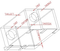
The optimization problem aimed to determine the optimal thicknesses of the lathe headstock housing walls, ensuring maximum rigidity while preserving the original mass.
The deformations of the spindle bearings referenced to the representative point (cutting area) were utilized as the rigidity characteristics of the housing - as it directly influences the performance of the lathe (machining precision). Through the optimization process, this parameter was reduced by 38%.
Задача оптимизации заключалась в нахождении таких толщин стенок корпуса, при которых он бы имел максимальную жесткость при сохранении своей исходной массы.
В качестве характеристики жесткости корпуса использовались его смещения, приведенные к характерной точке (к зоне резания), смещения которой определяют эксплуатационные характеристики станка (точность обработки деталей). Результатом оптимизации явилось снижение смещений корпуса, приведенных к характерной точке, на 38%.

Structural analysis of lathe headstock housing using DesignSpace
Расчет силовых смещений корпуса шпиндельной бабки токарного станка с помощью программы DesignSpace [1]
The displacements of the spindle bearings resulting from the deformations of the headstock housing under cutting forces were calculated. The influence of normal contact deformations at the joint between the headstock housing and the bed was also estimated (two different options of the FEA model were considered, differing by its boundary conditions).
Рассчитаны смещения опор шпинделя под действием сил резания. Произведена оценка влияния нормальных контактных деформаций в стыке корпус-станина на результаты расчета (рассматривались два варианта расчетной схемы, отличающихся друг от друга условиями закрепления).
 Imposing interconnections on parameters during design optimization
Наложение взаимосвязей на параметры при оптимизации конструкций [2]
Various methods of imposing «A < B» type constraints between design variables to optimize structures in Ansys were reviewed. The method of imposing such constraints without introduсing additional state variables was presented.
Рассмотрены различные способы наложения взаимосвязей типа «A < B» между переменными проекта при оптимизации конструкций в Ansys. Указан способ наложения таких ограничений без введения дополнительных переменных состояния.
 Setting up the Ansys GUI
Настройка графического интерфейса программы Ansys [2]
The key GUI configuration options of Ansys are reviewed, as well as the options for its saving and autoloading.
Рассмотрены основные опции ANSYS, касающиеся настройки графического интерфейса, а также возможности для их сохранения и автоматической загрузки.
 Ray Browell, Guoyo Lin
The Power of Nonlinear Materials Capabilities (Russian translation)
Мощь нелинейных возможностей
(перевод выполнен Рубцовым Б. Г. и Сергейкиным О. А.) [3]
Обзорная статья о моделировании материалов с нелинейными свойствами в ANSYS. Классификация и описание моделей материалов ANSYS.
Статья опубликована и переведена еще в 2000 г. и была приурочена к выходу ANSYS 5.6, однако практически вся информация из нее применима вне зависимости от версии ANSYS.
 Chernyansky P. M., Sergeykin O. A.
Analytical and Experimental Evaluation of the Rigidity of a Turning Center's Bed
Чернянский П. М., Сергейкин О. А.
Расчетная и экспериментальная оценка жесткости несущей системы токарного обрабатывающего центра [4]
An evaluation was conducted to assess how the machining precision is affected by the structural deformations of the bed under the weights of moving parts (the headstock and tool supports).
The machining accuracy was evaluated by deviations of diametrical and longitudinal dimensions of machined parts. These deviations components, in its turn, evaluated by reduction bed deformations (under the weight loads) to the cutting zone. Bed deformations were calculated by finite element analysis in Ansys.
An experimental study was also conducted to compare the calculated values with the experimental ones.
Произведена оценка влияния на точность станка силовых смещений несущей системы, возникающих под действием веса подвижных узлов (суппорта и шпиндельной бабки).
Точность станка характеризовалась погрешностями диаметральных и продольных размеров обрабатываемых деталей. Cоставляющие погрешностей размеров, в свою очередь, определялись путем приведения силовых смещений несущей системы (под действием весовых нагрузок) к зоне резания. Силовые смещения рассчитаны методом конечных элементов в программе ANSYS.
Также выполнено экспериментальное исследование с целью сравнения расчетных значений силовых смещений с экспериментальными.
 Chernyansky P. M., Sergeykin O. A.
Calculation of Shape Deviations of Machined Parts Caused by Structural Deformations of an Ultra-Precise Lathe Bed
Чернянский П. М., Сергейкин О. А.
Расчет отклонений формы обрабатываемых деталей, обусловленных деформациями несущей системы сверхточного токарного станка [5]
Значительная часть контента тут была перенесена с моего старого сайта
Documentation for Ansys and Nastran | Документация по Ansys и Nastran
My articles on practical applications of finite element method, tutorials for Ansys and Patran.
Мои статьи о практическом применении метода конечных элементов, а также учебные материалы по Ansys и Patran.

Прочностные расчеты для авиастроения – примеры моих работ с использованием Nastran и Patran
See also:
https://www.nytimes.com/2001/05/26/business/boeing-s-russian-edge.html (full text: part 1, part 2)
https://eislab.gatech.edu/projects/boeing-psi/ (methodology)
 Parametric optimization of fluoropolymer bellows for intravascular robot propulsion system in Ansys
Параметрическая оптимизация фторопластового сильфона для движителя внутрисосудистого робота в Ansys
 Programs for structural analysis and design optimization developed by me for my thesis – screenshots and brief description
Программы для расчетов на жесткость и оптимизации, разработанные мною при подготовке диссертации – скриншоты, краткое описание
Sergeykin. O. A.
The Influence of Structural Deformations of Machine Tool Body Parts on Machining Precision / PhD (Candidate of Technical Sciences) Thesis
Сергейкин О. А.
Влияние силовых смещений корпусных деталей на точность станков / Диссертация на соискание ученой степени кандидата технических наук
Thesis (in Russian) | диссертация
Abstract (in Russian) | автореферат диссертации
Essay (in English) | реферат для кандидатского экзамена по английскому языку
My thesis focuses on the technology and equipment for mechanical machining, specifically on the subject of shape optimization of machine tool body parts. The primary objective of the research is to address challenges such as enhancing part stiffness without increasing its mass, reducing part mass without compromising its stiffness, or similar optimization problems.
To conduct shape optimization of body parts, a reliable tool for strain and stress calculations is essential. Due to the complex geometry of body parts, analytical methods are not applicable for accurate calculations.
Finite element analysis is actually the most reliable tool for performing calculations on complex body parts. Nowadays, numerous software are available that specialize in conducting finite element analysis. I utilized the Ansys software due to its extensive range of features for both finite element analysis and shape optimization.
Design optimization is a methodology used to find the optimum best possible design that satisfies all specified requirements while minimizing certain factors such as weight, surface area, volume, stress, cost, and so on. In other words, the optimum design aims to be as efficient and effective as possible.
Virtually any aspect of design can be optimized: dimensions, placement of supports, cost of fabrication, natural frequencies, material properties, and so on.
Ansys provides two optimization methods to cater to a wide range of optimization problems. The subproblem approximation method is an advanced zero-order method that can be effectively utilized for various engineering problems. The first-order method relies on design sensitivities and is particularly suitable for problems that demand high accuracy from optimization process.
For both the subproblem approximation and first-order methods, the software follows a series of analysis-evaluation-modification cycles. This means that the software conducts an analysis of the initial design, evaluates the results based on predefined design criteria, and makes modifications to the design as required. This iterative process continues until all specified criteria are satisfied, resulting in an optimized design that meets the desired objectives.
In addition to the two optimization techniques mentioned, Ansys provides a range of strategic tools that can further enhance the efficiency of the design process. One such tool is the ability to perform random design iterations. This allows for a more comprehensive exploration of the design space and helps identify potential optimal solutions.
Note: The documents linked below are in Russian, but almost all of them have lots of self-explaining illustrations.
 Evaluation of the bearing capacity of the diamond mine anti-filtration screen
Оценка несущей способности противофильтрационного экрана алмазного рудника
Stress calculations were performed for the composite concrete anti-filtration screen in the diamond mine (kimberlite pipe) under the combined loads of the screen's own weight and water pressure during pit filling.
Представлены результаты выполненного мною расчета напряжений в бетонном противофильтрационном экране алмазного рудника (кимберлитовой трубки) при нагружении весом экрана и давлением воды, заполняющей карьер.

Расчет силовых смещений несущей системы металлорежущего станка МК6510Ф4 при использовании чугунной станины (отчет)

Расчет силовых смещений несущей системы металлорежущего станка МК6510Ф4 при использовании бетонной станины (отчет)
 Experimental study of structural deformations of the MK6510F4 lathe bed (report)
Экспериментальное исследование силовых смещений несущей системы металлорежущего станка МК6510Ф4 (отчет)

Расчет силовых смещений несущей системы металлорежущего станка МК6521Ф3 (отчет)

Оптимизация формы корпусных деталей металлорежущих станков с помощью программы Ansys [1]
The optimization problem aimed to determine the optimal thicknesses of the lathe headstock housing walls, ensuring maximum rigidity while preserving the original mass.
The deformations of the spindle bearings referenced to the representative point (cutting area) were utilized as the rigidity characteristics of the housing - as it directly influences the performance of the lathe (machining precision). Through the optimization process, this parameter was reduced by 38%.
Задача оптимизации заключалась в нахождении таких толщин стенок корпуса, при которых он бы имел максимальную жесткость при сохранении своей исходной массы.
В качестве характеристики жесткости корпуса использовались его смещения, приведенные к характерной точке (к зоне резания), смещения которой определяют эксплуатационные характеристики станка (точность обработки деталей). Результатом оптимизации явилось снижение смещений корпуса, приведенных к характерной точке, на 38%.

Structural analysis of lathe headstock housing using DesignSpace
Расчет силовых смещений корпуса шпиндельной бабки токарного станка с помощью программы DesignSpace [1]
The displacements of the spindle bearings resulting from the deformations of the headstock housing under cutting forces were calculated. The influence of normal contact deformations at the joint between the headstock housing and the bed was also estimated (two different options of the FEA model were considered, differing by its boundary conditions).
Рассчитаны смещения опор шпинделя под действием сил резания. Произведена оценка влияния нормальных контактных деформаций в стыке корпус-станина на результаты расчета (рассматривались два варианта расчетной схемы, отличающихся друг от друга условиями закрепления).

Наложение взаимосвязей на параметры при оптимизации конструкций [2]
Various methods of imposing «A < B» type constraints between design variables to optimize structures in Ansys were reviewed. The method of imposing such constraints without introduсing additional state variables was presented.
Рассмотрены различные способы наложения взаимосвязей типа «A < B» между переменными проекта при оптимизации конструкций в Ansys. Указан способ наложения таких ограничений без введения дополнительных переменных состояния.

Настройка графического интерфейса программы Ansys [2]
The key GUI configuration options of Ansys are reviewed, as well as the options for its saving and autoloading.
Рассмотрены основные опции ANSYS, касающиеся настройки графического интерфейса, а также возможности для их сохранения и автоматической загрузки.
 Ray Browell, Guoyo Lin
The Power of Nonlinear Materials Capabilities (Russian translation)
Мощь нелинейных возможностей
(перевод выполнен Рубцовым Б. Г. и Сергейкиным О. А.) [3]
Обзорная статья о моделировании материалов с нелинейными свойствами в ANSYS. Классификация и описание моделей материалов ANSYS.
Статья опубликована и переведена еще в 2000 г. и была приурочена к выходу ANSYS 5.6, однако практически вся информация из нее применима вне зависимости от версии ANSYS.
 Chernyansky P. M., Sergeykin O. A.
Analytical and Experimental Evaluation of the Rigidity of a Turning Center's Bed
Чернянский П. М., Сергейкин О. А.
Расчетная и экспериментальная оценка жесткости несущей системы токарного обрабатывающего центра [4]
An evaluation was conducted to assess how the machining precision is affected by the structural deformations of the bed under the weights of moving parts (the headstock and tool supports).
The machining accuracy was evaluated by deviations of diametrical and longitudinal dimensions of machined parts. These deviations components, in its turn, evaluated by reduction bed deformations (under the weight loads) to the cutting zone. Bed deformations were calculated by finite element analysis in Ansys.
An experimental study was also conducted to compare the calculated values with the experimental ones.
Произведена оценка влияния на точность станка силовых смещений несущей системы, возникающих под действием веса подвижных узлов (суппорта и шпиндельной бабки).
Точность станка характеризовалась погрешностями диаметральных и продольных размеров обрабатываемых деталей. Cоставляющие погрешностей размеров, в свою очередь, определялись путем приведения силовых смещений несущей системы (под действием весовых нагрузок) к зоне резания. Силовые смещения рассчитаны методом конечных элементов в программе ANSYS.
Также выполнено экспериментальное исследование с целью сравнения расчетных значений силовых смещений с экспериментальными.
 Chernyansky P. M., Sergeykin O. A.
Calculation of Shape Deviations of Machined Parts Caused by Structural Deformations of an Ultra-Precise Lathe Bed
Чернянский П. М., Сергейкин О. А.
Расчет отклонений формы обрабатываемых деталей, обусловленных деформациями несущей системы сверхточного токарного станка [5]
The deviations of diametrical and longitudinal dimensions of machined parts, as well as the cylinder shape deviations, caused by the deformation of an ultra-precise lathe bed were calculated under the loading by air pressure in the aerostatic guides of the moving parts (the tool support and headstock support).
The calculation was performed by reducing the deformation of the aerostatic guides to the cutting area, considering different locations of both the cutting area and the moving parts of the machine tool. The deformation of the bed under the applied load was calculated using finite element modeling in Ansys.
Вычислены составляющие погрешностей обработки диаметральных и продольных размеров и отклонения формы обрабатываемых деталей, обусловленные силовыми смещениями несущей системы сверхточного токарного станка, возникающими при ее нагружении давлением в аэростатических направляющих подвижных узлов (суппорта и шпиндельной бабки).
Их расчет производился путем приведения силовых смещений к зоне резания с учетом возможности различных вариантов расположения, как самой зоны резания, так и подвижных узлов станка. Расчет силовых смещений выполнен методом конечных элементов в Ansys.
Overview of Ansys Optimization Capabilities
Обзор оптимизационных возможностей программы ANSYS
The description of the methods and tools for parametric design optimization available in ANSYS is presented. This includes a review of their capabilities and algorithms.
Представлено описание методов и средств параметрической оптимизации конструкций, доступных в ANSYS. Рассмотрены их возможности и алгоритмы, лежащие в основе их работы.
 MSC.Patran macros (PCL, version 2003 and above) for applying cosine-distributed loads to a circle or a cylinder (zip-archive)
Макросы MSC.Patran (2003 и выше, PCL) для приложения к окружности и цилиндру нагрузок, распределенных по закону косинуса (zip-архив)
The macros provide the application of distributed loads with a user-defined resultant force to a circle or a cylinder.
The radial component of the resultant force is distributed according to the cosine law on the half of the circle or cylinder (without applying negative pressures). The axial component is distributed uniformly.
Макросы обеспечивают приложение к окружности или цилиндру распределенных нагрузок с заданной равнодействующей.
Радиальная составляющая распределяется по закону косинуса по половине окружности или цилиндра (без приложения отрицательных давлений). Осевая составляющая распределяется равномерно.
Ввод данных неинтерактивный (см. инструкции в файлах с макросами).

Вероятностный анализ пластины, нагруженной поперечной силой(перевод и адаптация учебного примера по ANSYS, версия 5.7 и выше, из ANSYS 5.7 New Features Workshop Supplement выполнены Сергейкиным О. А.)
The use of the probabilistic analysis module /PDS (Probe Design) is studied, along with the static analysis of shell structures. The module was introduced in ANSYS 5.7.
Compared to the original version of the ANSYS documentation, an interactive procedure for analyzing the structure with an initial set of parameters has been added.
Изучается использование модуля вероятностного анализа /PDS (Prob Design), появившегося в ANSYS 5.7, а также статический анализ оболочечных конструкций.
По сравнению с исходным вариантом из документации ANSYS, добавлено описание процедуры расчета конструкции с исходным набором параметров в интерактивном режиме.

Расчет силовых смещений корпуса шпиндельной бабки токарного станка (учебный пример по DesignSpace, версия 5.0 и выше)
Structural analysis in DesignSpace is explored in this tutorial. The geometric model in SAT format is attached. The tutorial provides a step-by-step description of the analysis in DesignSpace.
Изучается использование DesignSpace для статических расчетов на жесткость. Прилагается геометрическая модель в формате SAT. Пошаговое описание расчета для одной из статей, представленных на этом сайте.
[1] Сборник трудов 1-ой конференции пользователей программного обеспечения CAD-FEM Gmbh в странах СНГ (Москва, 25-26 апреля 2001 г.)
[2] Сборник трудов 2-ой конференции пользователей программного обеспечения CAD-FEM Gmbh в странах СНГ (Москва, 17-18 апреля 2002 г.)
[3] ANSYS Solutions, 2000, Volume 2, Number 1-2
[4] Журнал "Станочный парк", №5, 2012
[5] Журнал "Станочный парк", №7, 2012
No comments:
Post a Comment